Welding Heads

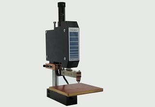
WBT-F01 Mechanical Precision weld heads
Features:
1. Application-specific modifications available
2. Outstand dynamic response
3. Outstand follow-up properties
4. Short welding time
5. Foot pedal mechanical drive electrodes
6. Build in welding force swtich
7. Provide stable weling force through springs
8. Adjustable electrode stroke
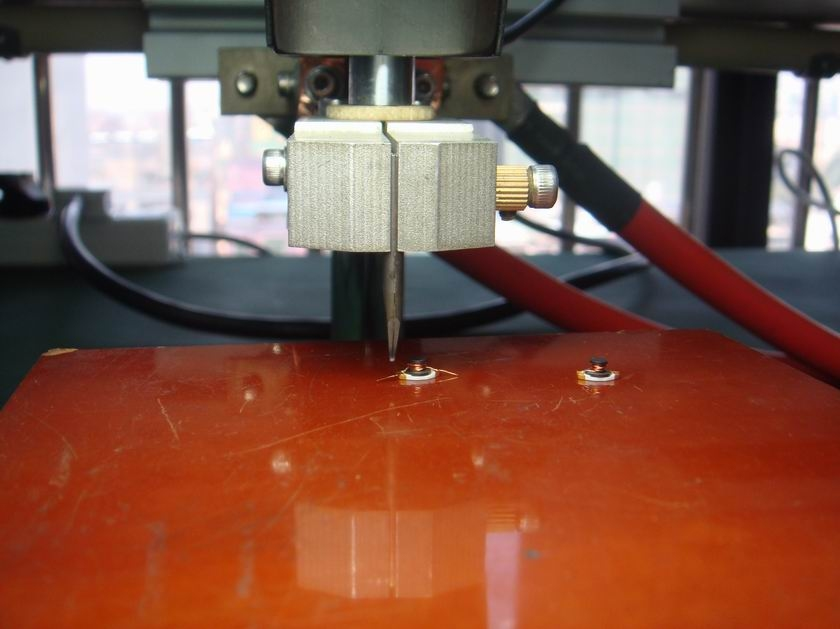
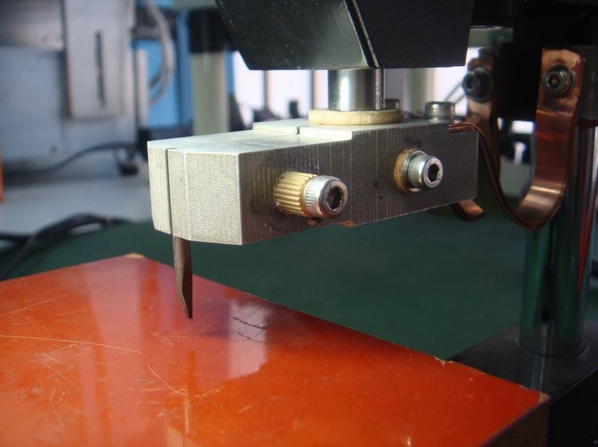
Product Details
Specification:
1. Net weight: 10KG
2. Dimension: 348mm x 193mm x 43mm
3. Welding force: 0.4KG - 10KG
4. Throat depth: 145mm
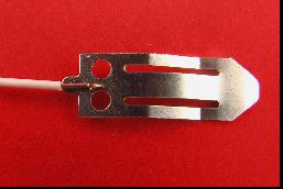
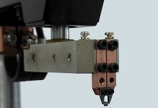
5. Electrodes: 3mm/6mm(diameter)
6. Driving method: Foot pedal
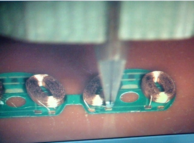
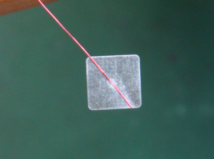
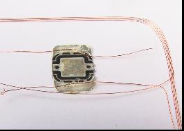
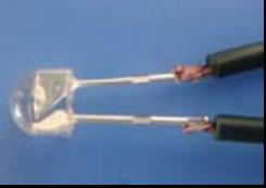
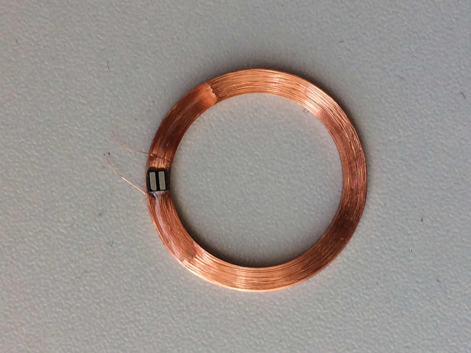
Applications:
Weld the Copper wire,need use the difference electrodes and holders